A lightweight CFRP housing example is far more than just a light replacement for a sheet metal or aluminum enclosure. It demonstrates what becomes possible when installation space, load paths, mounting points, temperature, and surface requirements are treated as a collective development challenge from the outset. Especially in motorsport components, mobile industrial systems, or high-end automotive applications, success is determined not by weight reduction alone, but by the precise coordination of design, laminate layup, and manufacturing processes.
A CFRP housing can protect sensitive electronics, stiffen functional cladding, or take on structural tasks. However, whether it truly leverages its advantages depends on the requirements. Simply transferring carbon into an existing metal geometry often wastes a significant portion of the potential.
Lightweight CFRP Housing: Example of a Control Unit Carrier
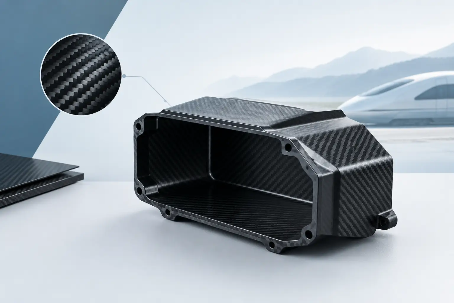
A practical example is a housing for a control unit in motorsport or a performance-oriented small series. The component must protect electronics against stone chips, splash water, vibrations, and local heating. At the same time, it is located in a tight installation space, must not unnecessarily increase vehicle weight, and must be reliably removable during maintenance.
An aluminum sheet version would require several individual parts: blanks, bends, welded or riveted joints, brackets, reinforcements, and potentially a separate visible cover. A purposefully designed CFRP housing can integrate the outer skin, stiffening, mounting flanges, and cover into a single component structure. This reduces joining effort and avoids the tolerance chains inherent in multi-part metal constructions.
The decisive factor lies in the load case. The housing does not need to have the same thickness everywhere. Areas around mounting bushings require different reinforcement than large, flat cover zones. At edges and radii, the fibre orientation must be diverted in a controlled manner. Where cable glands or screw connections are located, local reinforcement layers and suitable inserts may be required. The result is not a decorative carbon part, but a load-optimized technical component.
From Requirement Profile to Laminate Layup
Design begins with clear data: What masses are being supported? Which natural frequencies are critical? Are there constant vibrations? How high are the temperature peaks, and which media might come into contact with the component? For projects in the USA, additional requirements for fire protection, electrical insulation, environmental resistance, or customer-specific testing specifications may apply depending on the application.
The laminate layup is developed from these parameters. CFRP is anisotropic: its properties are direction-dependent. Fibers deliver their highest performance along their orientation. Therefore, fabric layers and, if necessary, unidirectional reinforcements are positioned not according to an optical pattern, but along the expected load paths. A 0/90 orientation can support bending and surface stiffness, while ±45-degree layers absorb shear forces and torsion.
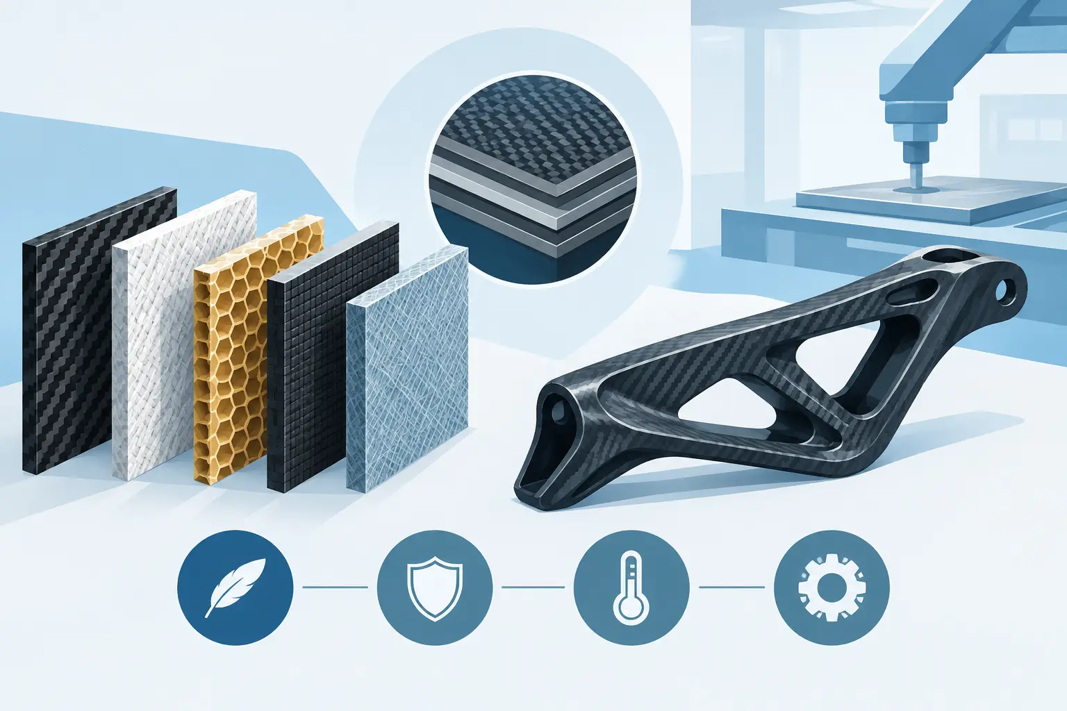
For a housing with a cover structure, a sandwich construction may be sensible. A lightweight core increases the effective component height and thus significantly increases bending stiffness without unnecessarily increasing the resin content. This is particularly suitable for large, flat, or only slightly curved surfaces. In zones with screw connections, high point loads, or tight radii, however, a sandwich core is often unsuitable or must be specifically notched and replaced by solid material areas.
Connection technology must also be determined early on. Metallic threaded bushings can be laminated in or integrated later. They require sufficient load-bearing laminate and a geometry that accounts for pull-out forces as well as repeated assembly cycles. Driving a screw directly into thin carbon is not a resilient solution for a high-quality technical application.
Why Prepreg and Autoclave Technology Make the Difference
For highly stressed housings with controlled surface quality, the prepreg autoclave process offers clear advantages. Prepregs are semi-finished fiber products pre-impregnated with a defined resin content. They enable a controlled laminate layup, clean drapability, and reproducible processing. In the autoclave, temperature and pressure compact the laminate under controlled conditions.
The results are low porosity, high fiber volume fractions, and consistent component quality. This is particularly relevant for thin-walled housings with a visible carbon surface: the fiber architecture remains precise, the surface can be finished to a high standard, and the mechanical properties are more reproducible from component to component than with less controlled processes.
This quality comes at a price. Prepreg material requires defined storage and process management. Autoclave capacity, tool quality, and cycle times influence cost-effectiveness. For large quantities with less demanding load cases, other processes may be more economical. However, for small series, prototypes, and components with high requirements for weight, precision, and visual quality, Prepreg in the autoclave is often the technically superior choice.
Tooling and Geometry Determine Series Capability
A successful CFRP housing is not just created during lamination. The tooling strategy influences dimensional accuracy, surface appearance, demoldability, and repeatability. A simple positive tool may suffice for an early form and fit prototype. For reproducible small series, stable, temperature-resistant tools with precisely engineered parting lines, flanges, and reference points are required.
Closed housing shapes are particularly demanding. Undercuts, tight internal radii, or complex sealing surfaces may necessitate multi-part tools. If a component is intended to seal against a gasket later, the corresponding contact surfaces must be manufactured not just to look clean, but to be geometrically defined. CFRP can deliver high precision, but this precision begins in CAD, mould making, and process planning.
Another point is trimming. After curing, contours, openings, and drill holes are often CNC-machined. This requires suitable clamping concepts so that the thin-walled component does not warp or become damaged. Clean edges and accurately positioned hole patterns are just as relevant for assembly as the carbon surface itself.
Evaluating Weight Savings Correctly
The question of weight savings cannot be answered with a blanket statement. Compared to a solid aluminum housing, CFRP can offer significant advantages. Compared to a consistently optimized, thin-walled sheet metal housing, the gap is smaller depending on the geometry. The greater advantage often arises through functional integration: when the cover, bracket, rib, and structure are combined into one composite solution, not only do the grams decrease, but so do the part count and assembly effort.
Weight must not be viewed in isolation. A housing that is a few hundred grams lighter does not justify a complex layup if it fails to meet thermal requirements or is difficult to handle during service. CFRP conducts heat significantly differently than metal. For power electronics, battery modules, or components with high heat dissipation, metallic cooling surfaces, thermal pads, or hybrid structures may be required. Carbon is no substitute for a well-thought-out thermal concept.
Electromagnetic shielding is also a special case. While CFRP possesses electrical conductivity, its shielding effectiveness depends on fibre orientation, resin system, joints, and the connection concept. For sensitive electronics, an additional conductive coating or a metal layer may be necessary. This must be tested before series release, not after installation.
Visible Carbon and Technical Function Must Align
A visible carbon housing conveys precision and performance when the fiber pattern, parting lines, and edge appearance are cleanly planned. However, this demand increases the requirements for tool surface, cutting, draping, and paint buildup. A layer intended to be optically perfect must not displace the mechanically necessary fibre orientation. Often, the visible top layer is therefore only one part of a technically optimized overall laminate.
UV stability, scratch resistance, and chemical exposure are secured via the appropriate finish. Different requirements apply to a component in the engine compartment than to a protected interior part. Transparent coatings can protect the visual appearance but do not replace a load-optimized basic design. Those who view a housing as a technical component make these decisions early and transparently.
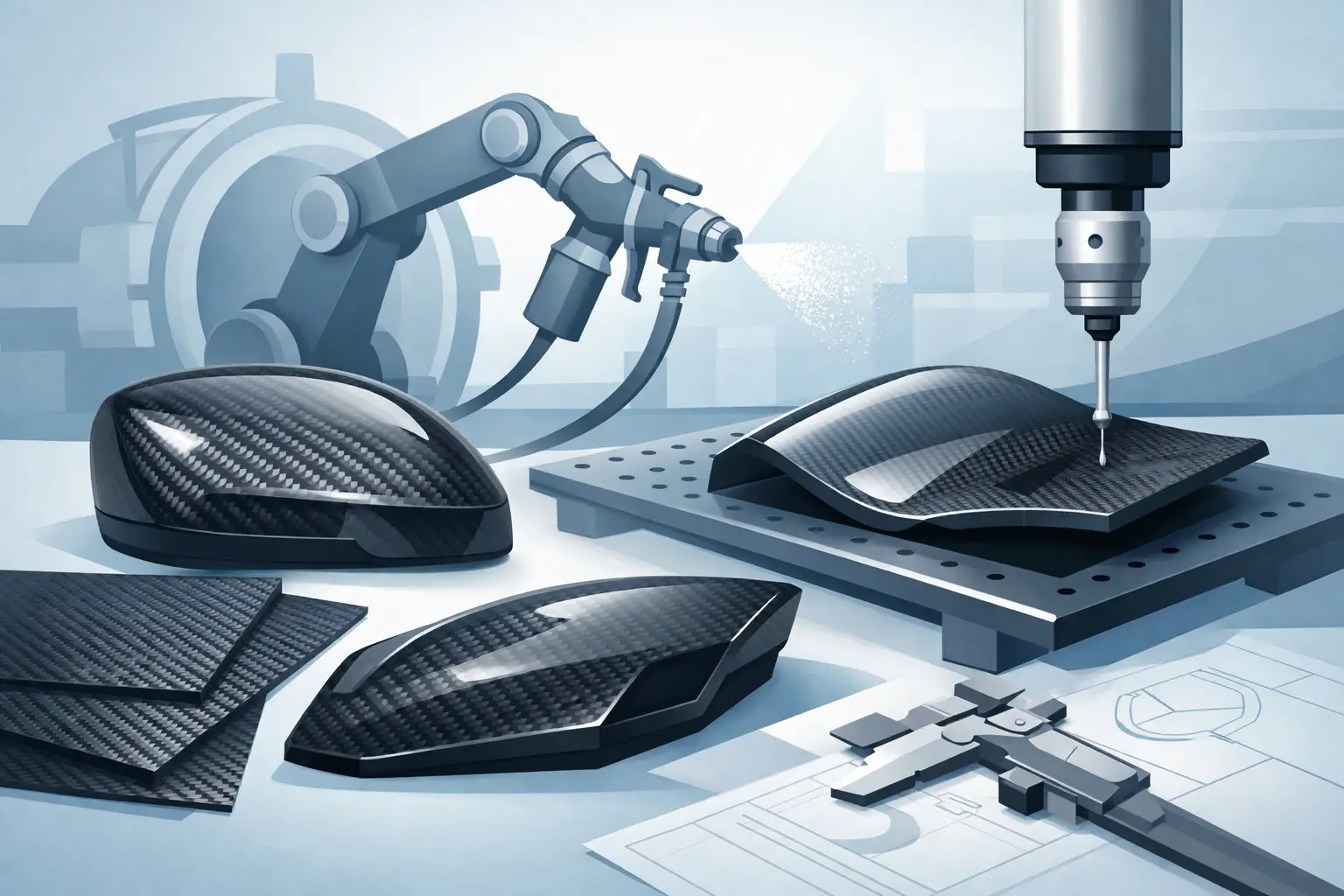
Composite World combines design, mould making, prepreg autoclave production, and CNC post-processing into a continuous process chain. This is particularly crucial when a prototype needs to be reliably transitioned into a reproducible small series.
A CFRP housing is economically and technically strong when its geometry utilizes the material’s unique characteristics: oriented fibers, integrated functions, defined connection zones, and manufacturing that leaves nothing to chance. The best example is therefore not the part with the most visible carbon structure, but the one that functions lighter, more precisely, and with lasting reliability in real-world use.